A switched-mode power supply (switching-mode power supply, switch-mode power supply, SMPS, or switcher) is an electronic power supply that incorporates a switching regulator to convert electrical power efficiently. Like other power supplies, an SMPS transfers power from a source, like mains power, to a load, such as a personal computer, while converting voltage and current characteristics. Unlike a linear power supply, the pass transistor of a switching-mode supply continually switches between low-dissipation, full-on and full-off states, and spends very little time in the high dissipation
transitions, which minimizes wasted energy. Ideally, a switched-mode power supply dissipates no power. Voltage regulation is achieved by varying the ratio of on-to-off time. In contrast, a linear power supply regulates the output voltage by continually dissipating power in the pass transistor. This higher power conversion efficiency is an important advantage of a switched-mode power supply. Switched-mode power supplies may also be substantially smaller and lighter than a linear supply due to the smaller transformer size and weight.
 SMPS: means Switch Mode Power Supply, they are Digital in Nature.They step down voltage by "switching" it on and off, hence their name.
SMPS converts AC Voltage to DC voltage. All the computer parts work on DC supply.SMPS supplies DC voltage through connectors on Motherboard and various other devices.
As you can see back side of SMPS. FAN is used to dissipate/reduce the heat generated in SMPS. In Fig , there are two AC power sockets. One is for AC 220 V input to SMPS and the other is for output AC 220 V to your Monitor/LCD. In some SMPS there is only one socket for AC 220 V input to SMPS . In this case the monitor will take input supply directly from other power source.
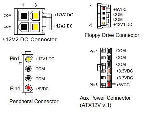
For the operation basics of SMPS PSU see our power supply. The original ATX systems had 20-pin main connector P1. When PCI Express® bus was introduced, PCIe cards needed up to 75W extra. To provide the additional wattage, the old part has been replaced by a new 24-pin P1. Accordingly, different ATX-style PSU may use different number of power wires: see the pinout diagram to the right. The colors in this chart represent recommended wire colors in the PSU cables. These diagrams reflect the front view. The colors are shown here just for reference (you won't see them from the front). The P1 uses Molex Housing Mini-Fit Jr. P/N# 39-01-2240 style (old part number was 5557-24R), contacts: 44476-1112. Mating motherboard header is Molex 44206-0007. The old socket was 39-01-2200 and the mating header was 39-29-9202. People often want to know what to do if there is a mismatch. Well, under certain conditions a new PSU can still be used with an old PC and vise versa.
 The rated current of the main Molex connector is 6A per contact. This means with the old 20-pin style you can't get more than 18A from 3.3V and 24A from 5V. That's why in early 2000's, some motherboards with 3.3V >18A and 5V >24A (mainly dual CPU AMD systems) used an auxiliary 6-pin power cable. It was removed from ATX12V spec v2.0 in 2003 because extra wires were added to P1.
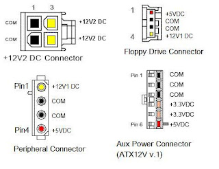 Serial Power ATA (SATA) connector are not 1:1. There are three pins for each voltage. One pin from each voltage is used for pre-charge in the backplane. The mating serial plug of ATA devices contains both signal and power segments. Some units may also have an optional 2x3 socket that can be used for auxiliary functions, such as fan monitoring and control, IEEE-1394 power source, and a remote sense of 3.3 V.
 Conclusion
transitions, which minimizes wasted energy. Ideally, a switched-mode power supply dissipates no power. Voltage regulation is achieved by varying the ratio of on-to-off time. In contrast, a linear power supply regulates the output voltage by continually dissipating power in the pass transistor. This higher power conversion efficiency is an important advantage of a switched-mode power supply. Switched-mode power supplies may also be substantially smaller and lighter than a linear supply due to the smaller transformer size and weight.
SMPS converts AC Voltage to DC voltage. All the computer parts work on DC supply.SMPS supplies DC voltage through connectors on Motherboard and various other devices.
As you can see back side of SMPS. FAN is used to dissipate/reduce the heat generated in SMPS. In Fig , there are two AC power sockets. One is for AC 220 V input to SMPS and the other is for output AC 220 V to your Monitor/LCD. In some SMPS there is only one socket for AC 220 V input to SMPS . In this case the monitor will take input supply directly from other power source.
For the operation basics of SMPS PSU see our power supply. The original ATX systems had 20-pin main connector P1. When PCI Express® bus was introduced, PCIe cards needed up to 75W extra. To provide the additional wattage, the old part has been replaced by a new 24-pin P1. Accordingly, different ATX-style PSU may use different number of power wires: see the pinout diagram to the right. The colors in this chart represent recommended wire colors in the PSU cables. These diagrams reflect the front view. The colors are shown here just for reference (you won't see them from the front). The P1 uses Molex Housing Mini-Fit Jr. P/N# 39-01-2240 style (old part number was 5557-24R), contacts: 44476-1112. Mating motherboard header is Molex 44206-0007. The old socket was 39-01-2200 and the mating header was 39-29-9202. People often want to know what to do if there is a mismatch. Well, under certain conditions a new PSU can still be used with an old PC and vise versa.

No comments:
Post a Comment
Note: only a member of this blog may post a comment.